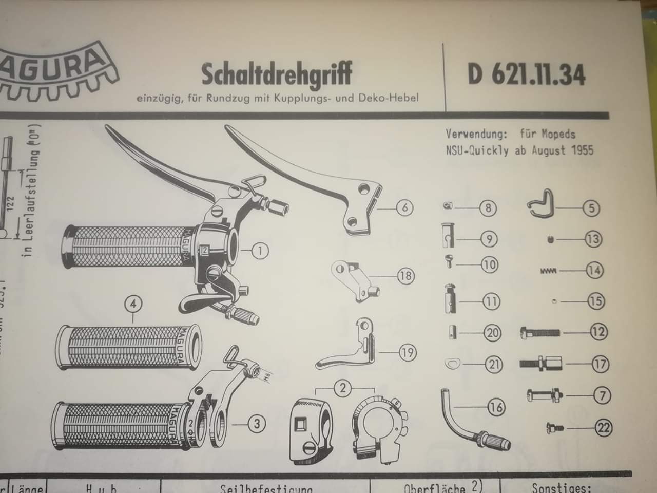
Gear change control
This bike needs a complete new set of cables, many of which seem to have been replaced with naked Bowden cable cobbled together with solderless nipples. The gear change also has a problem in that although it does shift the gears, it wont stay in any gear you select but always slips back to second. I suspected that the control detents or fixed positions were damaged so the hand grip is going to have to come off for inspection. This grip is complex since it includes the clutch cable lever, decompression cable terminus and lever as well as the gear cable itself. Luckily as a two-speed bike there is only one gearshift cable. I took some general views before dismantling.


 |
| Add caption |


Views of the movable section, note gear indications molded into the metal and bracket for mounting the clutch lever. I will paint the numbers to make the markings more visible.

 |
| Note slot at rear into which the teeth of the fixed section should fit. |
The hand grip slips off once the clamp screw is released. The hand grip is in 2 sections; an inboard fixed section attached to the bars and a rotating section attached to the cable that can slip within the fixed section to move the cable. A window through the fixed section shows a gear indicator on the rotating section beneath to show the gear selected. The clutch is attached to the movable section and the decompression system to the fixed part. In my case when the grip came off the handlebars the two sections simply separated. The gear change cable can only be removed by levering the grip flange away from the control

|
| Decompression lever. Note the small hole to the left of the lever attachment screw. At first this appeared to be empty, but inspection showed that in fact there is a small spring inside this. Note teeth on this section (top left) |
|
| Indicator section- is there something missing from the slot seen here at the rear of the body section to engage with the teeth on the fixed section. |
|
| Decompression terminal shares its mounting screw with the bar clamping screw. |
|
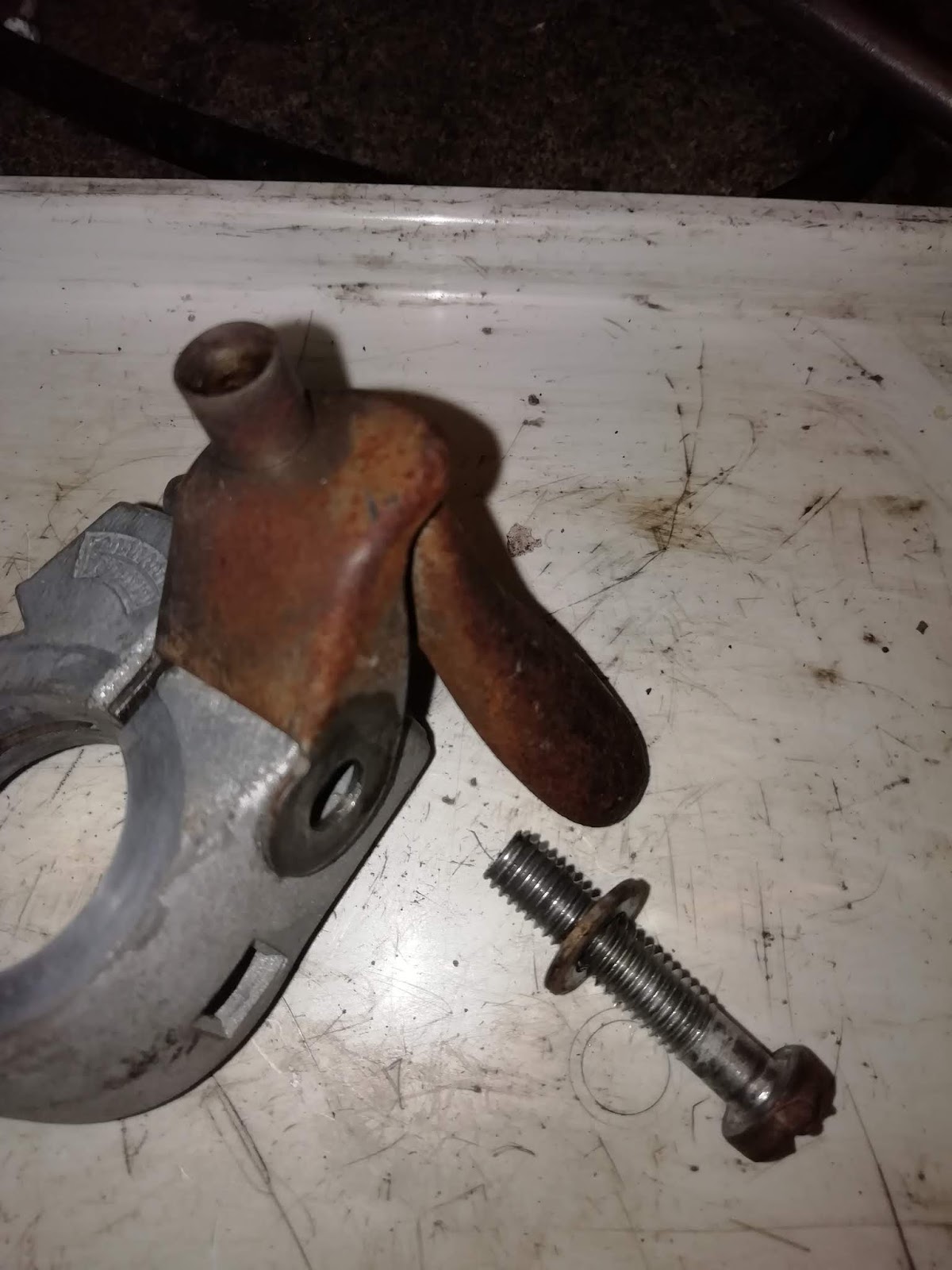
| Fixed section; Decomp lever removed. Note the row of pits that serve as detents giving a positive indication of gear selection. |


I received the grub screw, it turned out to be an M5 0.8 thread. It was clear that this could never have fitted into my control as the hole was only 3mm in diameter and unthreaded. I think that at some point the design was changed and the grub screw was omitted. The hole was then left blind to retain the spring and ball. However, the grub screw presumably would allow spring pressure to be adjusted which seems a useful feature. Accordingly I drilled the hole through from the top at 4mm and than tapped it to M5x0.8. This should allow all the components to be introduced from the top and then pressed into position using the grub screw to compress the spring. They will however fall out when the control is disassembled which probably explains why they are missing in my control.

I inserted the spring and ball after the control was assembled and positioned on the handlebar. To my delight, this did indeed restore the positive feel to gear change when the clutch lever was in.
Unfortunately the ball soon worked loose and fell out. If using a ball retained this way then the boring of the socket requires careful control of depth and size. I think the threaded section needs to be flat bottomed so probably bored using a flat ended mill, the opening at the base needs to be smaller to prevent the ball from falling through. Fortunately there is a far simpler solution in the sprung ball detent pins are available in grub screw format, the smallest is M6. I ordered 5 "Sprung plunger, steet, standard spring" no. GN615-M6-K from Zoro UK and got 5 for around £3. Having failed in the attempt to use an integral ball above, I simply enlarged the bore of the hole and tapped it all the way through at M6. The sprung ball screw could then be inserted and its position adjusted when the gearchange was in position to make sure the detent pits were functioning (I did need to redefine these using a 5mm drill as they'd become worn into a track.)


It's also clear that the clutch lever is worn. When released the lever has 2 flanges which interlock with the teeth on the selector unit. Although mine did do this the effect was marginal because the lever was worn away forming a hook-like recess.

I was able to repair this section using the low temp aluminium brazing rods advertised for aluminium repair on ebay. Using a gas torch I could build up the missing material and then form it to shape by grinding and filing. The result was a definite improvement and now interlocked more positively, however I don't know how well it will last in use.


I replaced the grips on the controls. These were new Magura grips and they were very tight. They're not quite like the originals though and I did prefer the more linear design molding. I found that fixing was greatly assisted by putting the controls in the freezer for 4 hours. I could then soak the grips in hot water with a little washing up liquid and push them onto the chilled grips.
 |
| New grips on the controls |
No comments:
Post a Comment
Feel free to comment on this and add suggestions and provements