When I bought this bike it was actually the second one that I'd looked at. The first was described as freely turning when I bought it, but later the vendor contacted me to tell me that in fact the piston was seized in the bore. I pulled out of that sale, so when I found this one at Kempton Park I was quite pleased that the vendor immediately told me that it turned over freely and proceeded to peddle it like crazy to prove it. It seemed to me in fact, that perhaps it turned over too easily and there seemed to be almost no compression. Still, at least it was turning freely. The time has come now to investigate the motor and discover why there seems to be such low compression so time to remove the head.
Firstly disconnect the decompression cable- you can disconnect this at either end but as the head was gummed up it was easier to release the solderless nipple at the decompression lever.
 |
| Solderless nipple at lever end of decompression cable. |
My first clue that all was not well came when I discovered that the cylinder head nuts were simply finger tight, and unscrewed easily using a box spanner and finger pressure alone. In fact, removing the cylinder head was so simple that I had done so before I even thought of taking any photographs! The top of the piston was lightly carboned and the cylinder head itself clearly needed a decoke.
 |
| Inside cylinder head |
I then removed the barrel which just pulled off. At this point it became clear that in order to make the motor turnover freely (and presumably to ensure a good sale) the PO had removed all of the piston rings and only loosely reassembled the unit. I feel it would have been nice if he'd told me these things instead of emphasizing the fact that the bike turned over - when it was quite clear that it only did so because he had fudged it- Caveat Emptor eh? Sometimes my faith in human nature is a bit shaken. We're all enthusiasts- we could at least be upfront with each other. There was also a circular mark on the piston crown. The motor had clearly been seized at some point and the vendor had then freed it by hammering the piston down with some form of drift.

The good news was that the barrel itself appeared completely undamaged. There was some marking on the inside of the Chrome but absolutely nothing that could be detected with a fingernail it's more of a bloom in the finish than a scratch or damage. If this was a body part I'd have no hesitation in polishing it out- its that slight. Overall I think the bore has survived remarkably well.
 |
| Looking inside barrel- hard to picture the marks I mean |
Certainly I don't feel the need to buy a new barrel. I measured this one as best I could using Sealey bore gauges and discovered the measurement to be 39.395 with minimal ovality; this indicates a standard and unmodified bore. In fact it's impossible to bore these cylinders out since that would remove the chromium plating on the inside but nice to know that the wear isn't significant.
Sadly, things did not end there. Checking the piston and big end for play I discovered rapidly that the little end was clearly worn. Probably as a response to the hammering process that was used to free the piston. Of course the damage may have been there before hand, I can't really be sure. The big end was a little bit more difficult to interpret. There was no up-and-down movement which clearly indicates the bush is not completely useless. The bottom end also slid easily between the two crankshaft webs as indeed it is supposed to. However there did seem to be quite a lot of transverse tilt movement; i.e. without moving the big end, the top of the con rod could be tilted across the motor by some 5 to 10 degrees. I've no idea whether this indicates excessive wear or not. It could for instance imply that the big end bush has worn like a bell-mouth at each side, the centre section being unworn preventing up down movement but the opening towards each end allowing some tilting motion. Of course, there has to be some clearance between the crank pin and the big end bush and so some degree of tilting is to be expected. I am unsure exactly how much is excessive and consequently I don't know if the crankshaft needs any attention. Certainly changing the big end is a large job. It's not excessively difficult but it will be very expensive. A new crankshaft seems to be of the order of £180. However a new piston is relatively cheap at £40 for a piston set including new rings circlips and gudgeon pin and changing the piston itself is a relatively simple job that doesn't even require the motor to be taken out of the frame. I decided to press ahead and fit a new piston into the existing barrel, refit the head and test the motor to see whether it will run. I should then be in a better position to assess the state of the gearbox, the clutch and of course the big end.
The piston is attached to the conrod by means of the gudgeon pin, this is turn is locked into the piston with circlips at each end. The pin should be free sliding but in two-strokes tends to gum up in the piston and often needs a tool to remove it. NSU speak of a pin punch to knock the pin towards one side, but that sounds like a perfect way to strain the big end bearing... Hmmmmm. Larger motors usually use some form of puller but these were way too large for this motor.
Anyway the first step was to remove the circlips, there should be one each side of the pin.... LHS- no sign of a circlip
RHS circlip present and grooves for its removal.
I picked the pin out with needle nosed pliers. I couldn't find one on the other side so either this piston never had one or its been removed once already!- This could explain my tilting conrod ??? I do possess a pin extractor but this pin is too small for even the smallest fittings. I'm certainly not going to hammer this already dodgy fitting so I improvised a small valve spring compressor, receiving socket and small drift to force it out. This worked very well but it was fiddly holding everything in alignment. Given the tightness of the pin I tend to think it hasn't been removed recently.
 |
| Valve compressor, punch and receiving socket to remove gudgeon pin. |
Once removed I could examine the piston- rings obviously missing and their grooves a bit gummy. There were some longitudinal striations on the skirt but nothing matching them in the bore.
Given these marks on the piston- and the circular hammer marks on the crown I don't want to reuse this item. It could be cracked so rather than risk that I ordered an new piston kit complete with rings, pin and clips and 2 little end bushes (I only need one but I'm expecting that I might not get it reamed right the first time!). I also ordered 2 pairs of circlips in case I need to re-install the piston on a new crankshaft.
 |
| Piston crown showing circular hammer/drift mark |
Cylinder head and Decompression valve.
The decompression valve was jammed in this bike. It had to come out for cleaning and checking. I depressed the spring washer with a screwdriver and could then use the flat of the blade to push the "C" clip towards the valve stem and unclip it.
The C clip washer and spring just lift off. The valve itself was still jammed so I tapped it downwards with a wooden drift.
And pulled it through
It was simply gummed up with sticky deposits and carbon. I cleaned the stem on a brass wire wheel and cleaned the head thoroughly. I ground the valve in using lapping paste to generate a nice even grey seat to both head and valve

Before rebuilding the spring system and retaining it with a new "C" clip. Checking operation showed that it now moved freely.
Little end (Gudgeon pin) bush
I had already detected wear in the gudgeon pin/little end bush area, although the jury is still out on the big end I went ahead to renew the little end bush. I found that one of the old leading link suspn bushes was just about the right size to act as a driver for the bush. I made up a small extractor using some M6 studding, two nuts, a socket large enough to receive the bush and a stack of washers. I turned the end of the link bush a little in the lathe to create a step that could locate inside the little end bush as it pressed it in.
Components of home installer/remover for little end bush. Note the leading link bush was turned down for a mm or so to create a locating lip
 |
| Home assembled extractor |
This pushed the bush out easily but you have to take care that it pushes out straight. You can then fit the new bush using the same system but without the driver as you can push the new bush in with the washer alone. Insert the little end bush bevelled end first using some oil to ease it in. The bush has three lube holes for oil splash, so make sure one lines up with the groove in the top of the conrod.
 |
| New bush entering conrod |
... and home.
 |
| New bush installed. |
This process causes the bush to close up internally so it will need to be reamed out to fit the gudgeon pin before use.
Once reamed ... I used adjustable reamer H1 3/8-7/16" to ensure a nice sliding fit. Check for pin fit as you go adjusting the reamer by half a turn between attempts. The pin for this piston was noticeably larger than the old one.
Note added: I have now fitted several small end bushes and there is a variability. The bush used here was from Krippl and was too small to accept the gudgeon pin (even the old one) before reaming. It was a tight fit in the con rod eye and reaming was essential. I have found that some bushes appear larger internally and will accept the gudgeon pin before they are fitted. These presumably rely more heavily on being crushed to generate a tight sliding fit to the pin when they have been pressed into place. This makes them more sensitive to any wear in the eye of the con rod which would reduce the "crush" and hence the tightness on the gudgeon pin. If you do find your bush is of the larger type then check the con rod eye for wear before fitting; measure both side openings and if there is any difference insert the bush through the larger opening so that its only crushed as much as needed to fit the eye. Further if the Bush is relatively loose in the eye it can be secured with a little Loctite 620 high temp retaining compound or it might rotate in the eye and close the lubrication channel.

Before fitting the piston I inserted one of the pin circlips. Note that the cut out port in the piston skirt has unequal sides. The longer side should face rearwards and in this piston that was also indicated by the letter "A" on the crown
This piston has two identical rings. They are also symmetrical so there is no special orientation. Just align the gaps with the stops.
You have to heat the piston before the gudgeon pin will slide in easily. I used a hot air gun. You'll need a cloth to hold the hot piston.
Slip it in until it contacts the clip on the other side and then insert the second clip using needle nosed pliers.
You can the then ease the cylinder down on top of the base gasket. Its hard to find a small enough ring compressor but its easy enough to squeeze them in with fingertips as you lower the barrel. The cut-outs in the spigot are a big help.
Assembled the motor, but it wont start! Turns out I have no spark so time to dive into the magneto I think.
In the meantime I will check the final drive sprocket and remove the pedals.
The pedals are easily removed, unscrew the cotter pin nuts and tap the pins out to allow the pedals to rotate. and break the tapers. The retaining nuts are then undone (all normal threads to anticlock to remove).
The first thing I found was that there was a considerable end float on the pedal shaft, seems to be about 2 mm! This seems excessive but it could be acceptable considering that this is just a pedal shaft so this needs to be checked.
The pedal shafts can then be removed. The shafts are marked for left and right. The pedals can be unscrewed from the shafts but the Right hand shaft has a right hand thread (anticlockwise to unscrew pedal) and the left hand shaft has left hand thread (clockwise to unscrew pedal)
Before gaining access to the sprockets I needed to remove the drive chain, described under rear wheel removal.

I found the sprocket teeth were worn sharp and a few were chipped.The final drive sprocket was also in poor condition and so both will need to be replaced.
.


To remove the rear sprocket I will need to remove the rear wheel (see appropriate section). To remove the front sprocket I wedged it with some wood (handle of a wire brush was great) so that I could unscrew the retaining nut and remove it and its washer.
Removing the sprocket itself will need the correct puller. I'm told a three legged puller will work, but not in my hands. Maybe a beefier one would succeed. Anyway I don't want to damage anything so I got the dedicated tool. However at this point I was overtaken by events.
Removing the motor
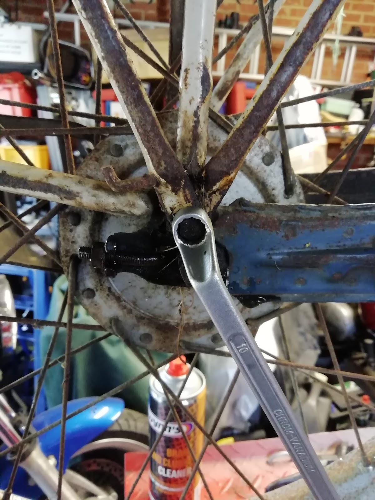
I would have liked to test the motor and change this sprocket in position as its easier to do both whilst it's in the bike and supported. However parts were late coming and I needed to get on with painting the frame and for this the motor needs to come out. Ah well its only 3 bolts and I can refit it later anyway. The three bolts are shown below, spanner is on the first of them
 |
| Engine mounting bolts, spanner shows rearmost bolt. |
 |
| Forward mounting bolt |
These bolts simply unscrew and the motor drops down. Note that there should be an anti shake washer under the head of each bolt (lhs) . One of mine was missing and one broken. All 3 bolts are installed from the left, the rear two have washer, spring washer and nut fitted on the right. The front-most bolt screws into a weld nut on the frame.
 |
| Engine mounting bolts remove- note missing anti-rattle washer on centre bolt and no nut needed on the front bolt. |
The motor is quite light and easily manhandled. However it's an awkward shape and doesn't stand up on its own. Any further work on the bench would need an engine stand. I was looking forward to making one but they are available at a very reasonable cost.
Replacing the crankshaft sprocket
The crank sprocket is on tight! I therefore invested in the special tool. I have to say I wasn't impressed. It is a solid lump of metal but it's been meanly thought out.
Firstly the bolt is so wide it will push on the nut if you leave it on to pretext the threads. It would have been easy to chamfer the end (as I did) to make sure it pressed safely on the crank. Also the press bolt was a coarse thread which means a lot of force is needed to shift the sprocket: a finer thread would have reduced this.
The main problem tho is that it measures 47mm across the flats. I don't know about you, but that's larger than most would have a spanner for. In fact it was larger even than my adjustable wrenches could cope with and obviously it won't take a socket. It would have taken a little longer but milling down to 28mm af would have been appreciated!
However, after much heaving I did remove the sprocket. The oil seal underneath looked in a poor state and was caked in crud. I will change it but I suspect I'll be stripping the motor later so I'll delay it and do it then if that's necessary or I'll do it on its own later if its not. I compared the old and new sprockets and received a nasty shock! The sprocket was so worn I was worried that my replacement was correct. This bike has clearly been greatly abused and this doesn't bode well for the condition of the still untested motor!
 |
| Old (lower) vs new (upper) sprockets. Wear is extreme! |
 |
| Greasy gritty deposit around the oil seal. This is presumably what has worn down the sprocket. |
 |
| New sprocket installed. |