Before starting this job its a great idea to assemble the bits you will need. I doubt you would be contemplating this unless a complete rebuild were on the cards so you will need a gasket set, new bearings, oil seals and sealing rings plus a few shims to set shaft clearances. All this is available from Roger Worton in the UK or Krippl in Germany. You may also need replacements for any screws that are missing or damaged, you could try simple screw suppliers first such as Margnor Fasteners frst but you will need to specify thread head shape and length. Buy grade 8 for strength.
You will also need some special tools- I find a flywheel extractor and a sprocket puller essential; a clutch decompression bracket and main gear holding tool will be useful too although these could be made or managed without. Should add that if you are dealing with a seized motor you may well need a crankcase separator as well.
Parts are cheaper if bought separately, so for bearings you will need two Crankshaft bearings (2x 6202C), two main shaft bearings (2 x 6201C for a 2-speed or 6201C + 6200C for a 3-speed) and a clutch bearing (6002C). All of these are open deep-grooved bearings lubricated by 2 stroke mix and oil spray. The clutch bearing can be sealed (6002 RS) although you could remove the seal on the inner face. All bearings are available from Simply Bearings and I would go for a quality bearing like SKF or FAG.
Oil seals are more tricky, all were originally green, metal cased seals that I can't source apart from the specialist NSU suppliers. The green colour could indicate that these are polyurethane seals but as this material is recommended only up to 200 deff (or around 100 degC) this seems unlikely. I would expect crankshafts to exceed this temp when running. However, I see no reason why viton seals wouldn't work perfectly (stable up to 200 deg C) or maybe even Nitrile which is much cheaper (130 deg C) and these are available from Simply as above. For a two speed you will need the following metric seals: 20 35 7; 12 32 7; 16 32 7. These three are specified as such in the quickly manual and would be best in viton as they are likely to encounter high temperatured. Two more are simply referred to as "sealing rings". These are for the pedal shaft and gear change shaft but my measurements suggest that they are 20 28 5 and 6. 12 3) that fits over the gear change shaft but it's got a thicker rubber than it's metal section so it's either 3 or 5 mm thick. As usual if you have information regarding the true sizes of any of these seals, or know a supplier of the metal cased versions please let me know and I'll happily include it (with attribution) in this blog.
I couldn't measure the O rings with any accuracy so these will need to come from a specialist but I'm told some of these (esp the clutch cup ring) don't work that well anyway so you may be best to stay with the originals.
I didn't want to risk my motor with ham-fisted manipulations so I bought an old, seized motor to take apart and work out what I was getting into. This is the account of the seized motor- skip it if you are interested in the real thing (see "stripping the motor part 3"). I'm not necessarily intending to rebuild this test motor, I don't have the funds and I suspect damage to the internals may be terminal anyway, but if it turns out not to be so bad then I might attempt repair. For the moment I'm only interested in the strip down.
The test motor
The motor I got was a 2 speed, but it had been partially stripped before and then loosely reassembled. Some parts are missing but hopefully it will still be of use. I had already removed the cylinder head and barrel which was very difficult because it had seized both at both the crank shaft and the piston in the barrel. I eventually succeeded only by holding the barrel in one hand and then placing a large protective washer on top of the piston and pounding that down with an impact socket drift and a hammer. It was very hard (easier with someone to hold the barrel for you) but this method ensures that the force is spent between piston and barrel and not transmitted to the big end bearings just in case they might be salvageable. In fact the piston did eventually clear the barrel, the rings appear to have melted seamlessly into it and the piston will be unusable. The barrel fared better and can probably be reused. Once the piston was out however it was immediately apparent that the main bearings are seized solid- there was no rotational movement of the shaft at all! The con rod would pivot fore-and-aft easily with no detectable up and down movement so the big end bearing may be OK but I think the main bearings are probably destroyed.
I then mounted the bottom end of the motor in the stand and photographed both sides.
 |
| left side motor, drive sprocket removed, clutch operating rod missing. |
 |
| Right side motor alternator present |
I removed the flywheel with a puller as usual.
Unlike my motor, the junction plate was still present here so I removed the clamp plate (refitting it for safe keeping as I will fit this to my own motor when rebuilding) and pulled the blue wire and HT wire back through the case grommet. Remove the two screws and washers holding the magneto back plate and take the back plate off.
 |
| Lighting wire clamp bracket and junction block yellow to blue wire junction. |
 |
| Magneto back plate removed. |
The brake lever is held on by a surface C clip which in my case was already missing and the lever then simply levers off (might be advisable to mark its position for refitting). The lever was very tight but it did come off eventually.
 |
| outer C clip was missing so the brake lever was levered off. |
There is another C clip beneath the brake lever so this is removed with circlip pliers.
 |
| removing the inner C clip |
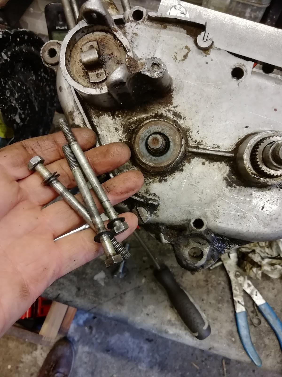
Next remove the 7 crankcase bolts from the left-hand side and one bolt on the right. In my case only 3 bolts were present (note all have washers) and the rhs bolt was missing too.
Before removing the LHS case its necessary to remove the circlip and washer from the gear change plunger on the RHS. In my case these had already been removed.
 |
| Gear change plunger- this has a groove for a circlip and a washer to engage with the gear change lever. These had already been removed before I got the motor. |
The LHS cover should then just pull off, it was very stiff but did eventually tap free.
I fashioned a broad flat lever from an old piece of conduit to lever the cases apart without damage.
 |
| Flat lever formed from conduit pipe. |
Once removed the workings were exposed.
 |
| Gearing below case, note clutch cup on crankshaft, large driving gear on main shaft and starter ratchet on pedal shaft |
 |
| Starter ratchet/pedal mechanism, this has 4 sealing O rings, 2 inside and 2 out, not sure how these should be renewed. There are also often adjustment shims under the slider but in my case these were missing, probably removed by the PO rather than unnecessary. |
 |
| Clutch cup and main shaft drive gear |
 |
| Inside left hand cover. |
The clutch cup is removed by firstly removing the base clip. The base clip has three lugs, one visible in this picture.
 |
| Clip lug at base of clutch cup. |
It wasn't clear how to remove this but I pushed the lug above with a screwdriver in towards the gear and downwards so that the clip was eased out of its groove. It could then be eased out progressively around its groove..
 |
| Lug pressed in towards the gear ad downwards to pop out of its groove. |
Until the clip dropped right out
 |
| Clip removed. |
The clutch cup itself can then be levered upwards- its recommended to use a special tool. in fact, as someone had been here before me it didn't need any leverage and simply pulled off by hand.
 |
| Mainshaft drive gear meshed with crankshaft visible after Clutch cup removed |
The clutch mechanism is then removed by unscrewing the top nut but...
1. Its under tension from the spring below
2. The shaft may turn instead of unscrewing the nut!
The first problem can be managed as the tension isn't great, but Krippl in Germany sell a special tool to compress the spring and preserve access to the nut. Simply fit it across the clutch using case bolts. I got this and it worked well. I think it will be more use in reassembly.
In order to stop shaft rotating there is another special tool- a lever which engages with the gear to prevent rotation. I dont have this but as my motor was siezed rotation really wasn't a problem at this stage!
 |
| Clutch compression tool fitted |
 |
| Clutch nut removed |
 |
| Clutch compenets as above. |
The components of the clutch can then be lifted off. These consist of the nut and 2 spring washers, spring top seat, spring and spring bottom seat pressed into clutch bearing. This bearing was very rough in action and obviously needed to be changed.
 |
| Clutch bearing turned over to show open ball face. |
The large main shaft gear can then be lifted off.
This exposes the top clutch cover which in my case lifted off.
to expose the clutch plates below. This bike has two lined plates sandwiching a metal plate.
 |
| Lifting off the clutch cover to reveal the plates. |
Lifting the plates out showed that the upper lined plate was missing and the uppermost was in fact the metal plate.
 |
| Lifting out the metal plate, in lined plate missing. |
... although the second lined plate was still present below the metal plate.
 |
| Removing the only remaining lined plate. |
This exposes the clutch centre. It should be held by a circlip in the grove around the shaft but once more in my case it had already been removed. This is however as far as I think the PO must have got in his motor strip because I found the centre to be very firmly fixed- and indeed may actually be melted into position depending on how extensive the siezure damage was to this motor. Once more the manual recommends using the special levers to ease this centre off the shaft but I'm informed via the Fb forum that its possible to use a puller or two offset screwdrivers instead. It seems to me that all three of these approaches risk bending the clutch centre flange on which the plates have to sit so I'll have to proceed carefully.
 |
| Clutch centre |
 |
| Clutch centre, there isn't much room to lever it. |
The offset screwdrivers worked quite well and if positioned carefully would lever up on the central boss rather than the clutch flange. I found the clutch centre was very tight and I had to use a hammer to tap the levers and knock the clutch up.
 |
| Offset screwdrivers, use a pair instead of the special levers (unless you have them!) |
 |
| Slip bent section under the flange and lever up on the boss. Use two, only one shown as I had to hold the camera! Should also use metal strips to protect the case as you lever. |
 |
| Using wooden Packers to protect the motor case whilst levering. Spin the clutch so as to lever from alternate sides |
The centre then lifted off.
 |
| Removing clutch centre from crankshaft |
 |
| Crankshaft oil seal revealed, mainshaft and gearing visible right behind case web. |
Looking behind the boss the screwdriver had marked it, marks limited to the strongest parts though. I used a file to remove any significant burrs. I'm assuming that the real tool levers are long enough to lever without hammering, and broad enough at the clutch end that they spread the load to prevent this marking.
 |
| Underside of clutch centre- some marking from my violent levering process. Marks are largely over the boss load bearing sections to avoid bending the peripheral flange. |
It's necessary to remove the nut and bolt holding the cases together. I've indicated its position on the rhs, but once more in my case it was already missing.
 |
| Position of nut and bolt that should be removed at this stage- in my case already gone! |
The cases should now separate so remove the two components of the pedal starter ratchet from the pedal shaft. These have odd names in the manual; foremost is called the "Locking member" and the hindmost is the "driver". Anyway these are free so slip them off now if not already done so.
You can now rotate the motor so that the lhs is uppermost and start to separate the cases. .

You can tap it carefully with a dead-stop or nylon mallet to start the separation. Here I came unstuck in that the cases just would not split... Presumably due to the seizure that was immobilising the crankshaft. I was eventually forced to refit the clutch nut flush and tap on the crankshaft ends to drive the cases apart and again to remove the crank from the bearings. This process is a complete no-no as it will almost certainly damage the crank alignment. However as this crank is seized already and its by no means certain that it could be repaired I wasn't too worried. I think if confronted by this situation again, I'd use a crankcase separator- I've ordered one now but sadly hadn't got one at this time.
** Just for info- this is the case splitter I had ordered- its a clone of the Tusk tool. Its tricky to find an orientation that works but it can be positioned on the pedal shaft as shown. Remember to fit the pedal securing nut flush with the end of the pedal shaft to avoid damage from the press.
 |
| Use of the case separator |
Anyway- without the press and with a lot of brute force the cases did at last start to move.
 |
| Cases starting to separate |
I could then slip the side case off revealing the state of the internals. The pedal drive shaft and gear looked good but the crankshaft was badly rusted
 |
| Inside centre case, very rusty crankshaft |
Even though this had removed one bearing the crank would still not rotate and it was apparent that the big end was seized solid as well
 |
| Crank won't turn and big end frozen |
There was quite a build up of rusty debris in the case under the crank webs. Presumably this is material that should be part of my motor!
 |
| Add caption |
Looking inside the case just removed showed that the main bearing was horribly rusted and had no movement in it.
 |
| Corroded and frozen main bearing. |
The crank was tapped out of the centre case using the same method and it eventually popped out to reveal an equally nasty and rusted main bearing on the other side.
 |
| rusty main! |

The pedal shaft is now free and can be lifted out.
 |
| Pedal shaft just pulls out. |
This reveals the gearbox which consists of three shafts. The gears themselves are installed on the shorter layshaft towards the bottom of the motor (note top as picture below is inverted). The sliding dog gearchange mechanism is on the mainshaft. The dog is moved by a sliding fork which is mounted on a separate gearchange control shaft. The gearchange fork is mounted on a smaller gear control shaft.
 |
| Gearbox components three shafts. Top left Layshaft with 2-speed gears, centre Mainshaft holding Gear change mechanism sliding dogs engaged with fork of gear control mechanism. Control mechanism mounted on gear control shaft above its spring right in picture. |
The gear change control fork is retained on the control shaft by a circlip and washer. The gears themselves are free to slide up.
 |
| Gear change mechanism, circlip and washer holding sliding fork on the shaft. |
There is an adjustment shim on top of the gears. The thickness of this is crucial to govern end float of the gear mechanism. This is determined by careful measurement of the cases and the gear column. If you aren't changing anything then this will probably be OK simply rebuilt as is. Its a shim rather than a thrust washer so I don't think it should wear easily. This is actually the first shim I've found in this strip down but Id expected others eg on the crank... perhaps this explains the pile of rust I found? (a little later I did find a rusty shim on the garage floor. I think this came from the crank when I removed it). I'll need to recalculate the shims required because I'll be using a different crank so I'm not too worried at this point. Anyway remove the shim with a magnet to lift it off and keep it safe.
 |
| Shim removed from 2-speed gear tower |
The gear tower then lifts off the layshaft.
As stated above the gear control mechanism (fork and spring) is on a separate gear control shaft. The fork engages with the gearchange dog on the mainshaft. The control mechanism is removed by pushing the circlip back.
 |
| Close up of circlip and washer on gear control shaft. |
... and remove it and the washer beneath.
 |
| Circlip and washer removed. Gear change fork then lifts off bringing the sliding dog with it. However wear grooves may jam the fork so it may need a tap to bring it off. |
 |
| another view of the gear control mechanism now circlip is removed. |
The components of the control mechanism then lift off the gear control shaft (bear in mind the fork may be retained by a wear ridge), followed by the sliding dog which slips off the mainshaft

 |
| Gear control removed, removing the sliding dog. |
Note that the dog will only slip down fully if its fitted one way round.
 |
| Components of Gear control mechanism as removed. Circlip, washer, fork and spring. The sliding manishaft dog is also shown. |
This leaves the mainshaft, layshaft and gear control shaft still fixed into the case. I don't think the gear control shaft is removeable but the mainshaft should come out of its bearing and this shaft should also have adjustment shims beneath it. Not surprisingly mine is stuck. The shaft terminates in a bearing, but as this is installed in a blind socket you can't tap the shaft out from behind. I didn't have a slide hammer that would attach to the shaft so I refitted the shaft sprocket nut, held this in the vice and tapped the case away from it. This actually pulled the bearing out of the case but left the bearing on the shaft.
 |
| Three shafts left in the case, mainshaft, layshaft and gear control shaft |
 |
| Mainshaft bearing removed revealing blind socket. |
 |
| bearing still attached to mainshaft so sprocket nut was reattached and held in a vice |
I didn't have a puller with narrow enough feet to pull the bearing off the shaft so I was forced to heat it with a hot air gun and then use a screwdriver inserted between bearing and dog pinion and twisted to force the bearing backwards.
 |
| Using a screwdriver to twist beating backwards. |
Note that there is a shim washer between the bearing and pinion.
 |
| Shim washer above bearing |
There is another washer (thrust) above the dog pinion.
 |
| Base mainshaft fittings, Bearing shim, lower dog, shim, mainshaft. |
=
A word about the crankshaft...

The crank was seized and rusty as well. Its very likely that my hammering will have upset the distance between the webs and thrown the thing out of balance. Looking at the views from both sides below it dows seem that the webs are no longer paralell- assuming that they originally were. However this crank was never going to be any use without a full rebuild anyway- and possibly not even then! It is possible to get a new conrod and bearing but this is expensive at £54 so I probably won't bother as I suspect a good used crank will be cheaper. I may try dismantling this shaft though as I am curious as to how it would be done. The problem is in re-assembling and balancing the assembly which I think is beyond the remit of the home mechanic. If the webs hadn't been knocked out of parallel then it may have been possible at home as I could have taken some reference measurements before starting, and then rebuilt to the same dimensions. As it is I'm not sure which if any measurements could be trusted although the measurement across the crankpin is likely to be closest.


The Von rod had always pivoted in the crankpin and the roller bearings looked shiny with no up\down play. The seizure is therefore between the conrod and the webs. There is a washer here which in my case seemed to be rusted on both sides. Application of WD40 and gentle persuasion gradually eased it loose to the point where the crank could rotate although it was still weeping rusty oil. I'm pleased to say that there was little side side play compared with that in my own motor but I'm not sure which is correct. The crank did of course suffer some considerable abuse during case separation do I'm not sure it's usable. I have ordered a used replacement do I'll compare the two when I receive that.


 There is another washer (thrust) above the dog pinion.


No comments:
Post a Comment
Feel free to comment on this and add suggestions and provements