Removing rear drive chain, wheel and sprockets
To remove the rear wheel you need to remove the drive chain. No problem as it's like a bicycle chain with a split link. This should be fitted with the closed side facing direction of chain movement. In my case it was yet something else wrong with my bike. Anyway force the open end backwards with the flat of a screwdriver, withdraw the link. This chain was worn so will be replaced.
The exhaust is also likely to get in the way so I removed that too. A single bolt holds the hanger inside the rear fork.
Gearbox sprocket looked worn. It needs a puller to remove it. I'm told a conventional 3 legged puller will do it, but it didn't in my hands. I had to buy the actual tool
I also removed the pedals, not strictly necessary but will make more room.
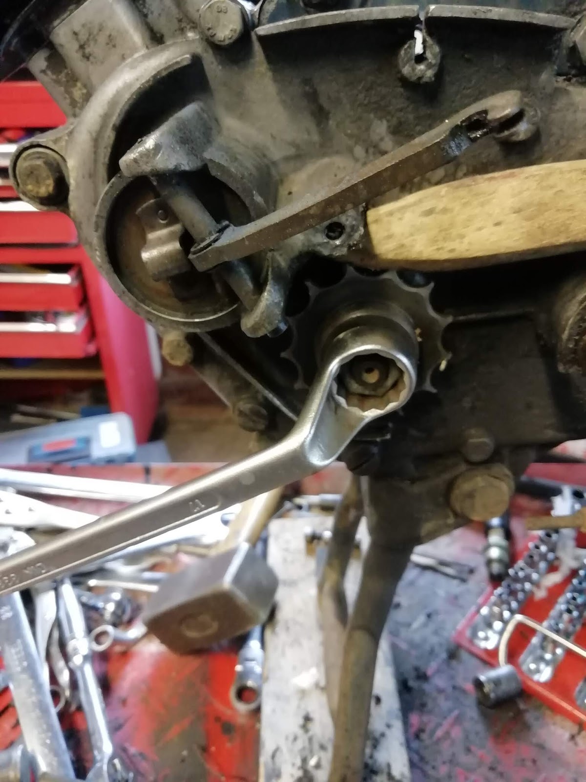
I unscrewed the nut on the gearbox sprocket, jamming it with the wooden handle of a wire brush to prevent it turning.
... And removed the nut and washer before using the puller.
The puller screws onto the sprocket and is tightened to remove it. But this tool was a bit of a disappointment. Firstly, If you just tighten it up as supplied then the end of the push screw is so
wide that it overlaps the threads on the sprocket shaft and will damage them as its tightened. It would have been easy to taper the end to avoid this as I did on the grindstone.

Secondly the body of the puller has flats milled in it. They could have been milled to any size but the manufacturers chose 37.5 mm across the flats. I don't know about you but my spanners don't go that large- in fact neither did my adjustables and I had to buy a new extra large one to cope. Why couldn't this have been milled to a more convenient size??
Anyway, it did eventually work and once removed the old sprocket was clearly in need of changing!
 |
| Wear on old vs new sprocket |
The oil seal behind was dirty and although it looked poor it didn't seem to be leaking. I have bought a new seal but I'll not change it now as I'm expecting to have to strip the motor down soon and change all seals and bearings.
 |
| Oil seal behind not looking good. I will clean this up for now. I'm expecting to replace all oil seals later when I do a rebuild |
 |
New sprocket installed
|
The rear mudguard is held by 2 stays that share their fork mounting with the rack carrier legs.
Remove the bolt to release all 4 struts.
Carrier is also held by a top nut and bolt.
Loosen the axle nut and tap the axle out towards the opposite side. Catch the spacer from the rhs which will drop out as the axle is removed towards the left. It's not necessary to release the chain adjusters but as I was expecting to change sprockets and chain so there was no point in preserving this setting. I slackened them off
Once removed the rear wheel can be finagled out. Remember to release the brake plate from its torque button on the inside of the lhs rear fork.
 |
| Torque button inside rear fork left |
Stripping the hub
I took several views of both sides of the hub before dismantling the wheel.
 |
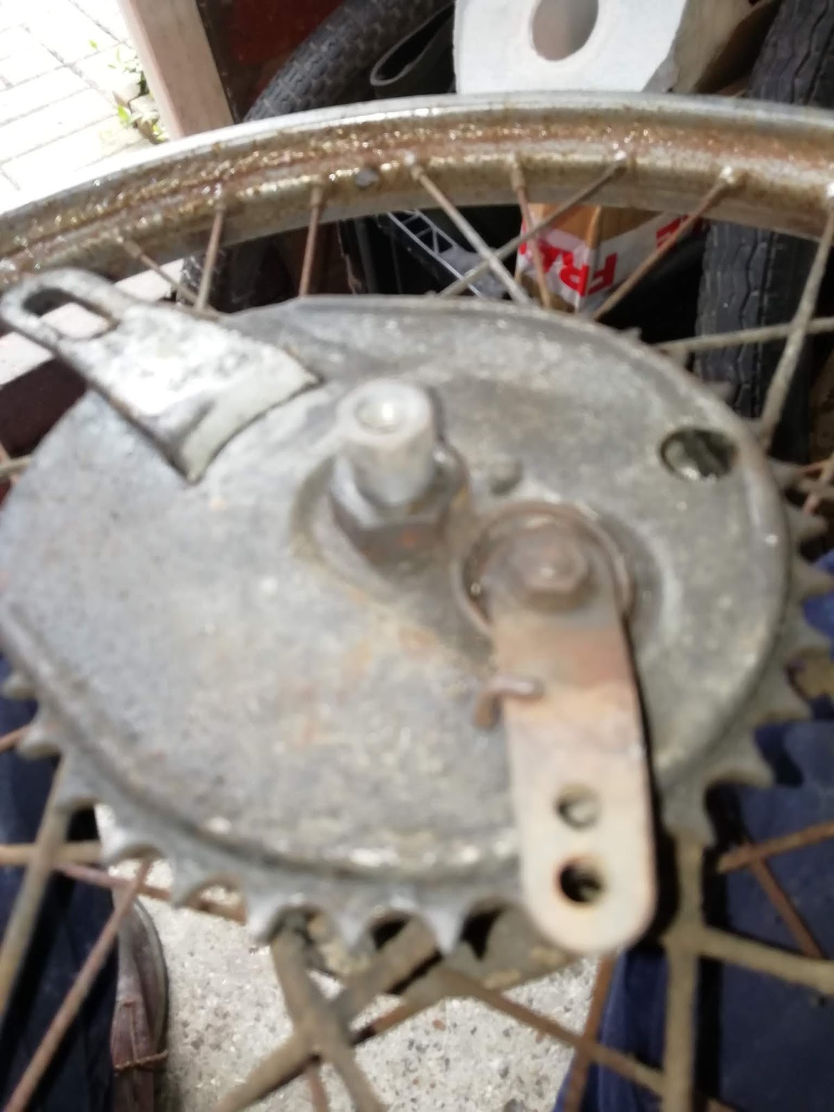
| Brake plate side (LHS) |
 |
| Plain side (RHS) |
 |
| Brake lever and spring |
The rear wheel rim was in poor condition with flaking chrome shedding razor sharp shreds, most spokes are loose and all are rusty so this wheel will need rebuilding.
 |
| Lifting chrome |
Dismantling the rear brake
The brake arm is held on with a nut and spring washer, in this pic the axle is still present.
Removed
I've had problems aligning the brake arm on the front wheel because I forgot to mark its position. This time I remembered and used a centre punch to indicate the alignment of the arm and the shaft.
 |
| Using a centre punch to mark position of brake arm on actuating spindle. |
The arm then levers off and the spring lifts out.
To remove the brake cover plate unscrew the 22mm nut, hold the back plate arm to steady against the spanner.
When this nut is removed the brake cover plate will lift out of the hub, bringing with it the brake back plate.
 |
| Brake cover plate/back plate assembly |
The brake shoes and anchor spring are mounted on the brake back plate, the cover lifts off
 |
| Rear view- shoes and spring |
The spring can be levered out and then the shoes removed. Mine were in good condition so I just cleaned them with brake and clutch cleaner and will refit. These shoes are probably not the originals because they are bonded not riveted. Once the shoes are out, the actuating spindle pushes out, it didn't seem very worn but will need cleaning and re-greasing.
I set both the cover and back plates to de-grease and de-rust before I resprayed them with engine aluminium paint. I could then attack the hub.
Note that there is a shim above the bearing cone/plug and below the back plate- keep this safe.
 |
| Shim below brake back plate |
Removing the bearings
As the front wheel, in this model quickly (and older models) the bearings are a three part system consisting of a threaded outer cone or plug against which the bearings run, these being pre-assembled into a cage for convenience of installation. The bearing cage is pushed by the plug up against an inner bearing shell pressed into the hub so that the bearings are held snugly and run in the shaped grooves on the plug/cone on one side and the shell on the other. To remove the bearings you need to unscrew the bearing cone/plugs. The manual calls for you to unscrew the right hand plug but there's no way to control which side will actually unscrew. I don't think it matters so use a 15mm spanner on the flats of each plug and unscrew.
In my hands the rhs unscrewed completely and could be removed by pulling it out of the oil seal.
 |
| rhs bearing plug being removed. this leaves the oil seal and bearing cage in position. Note the shaped groove in the plug/cone in which the bearings run. |
The oil seal itself can be levered out with a screwdriver.
 |
| oil seal removed |
The manual then calls for the opposite side bearing cone/plug to be tapped out. Use a soft drift inserted from the opposite side and feel for the edge inside.
Tapping this will then drive the opposite bearing cone out complete with oil seal, bearing cage and inner spacing tube. The spacing tube has to be separated from the bearing cone and there's no way other than gripping the spacer in a vice and unscrewing the cone, but take care not to flatten it.
 |
| a little clearer when de-greased. |
 |
| Brake plate side (LHS) bearing cone separated from the inner spacer tube. |
Note that there is a crushable internal spacer that fits inside the central tube not visible in this picture. This needs to be saved and refitted when the new bearing is assembled.
Removing the chain sprocket
The rear sprocket is held on by 6 special M5 1.2mm shoulder bolts with a flat ground on their heads to accommodate the shape of the hub.
(I had lost a few and replaced those with 1mm M5 socket cap bolts but had to swap the spring washer for a shake proof and threadlock.)
Remove the 6 nuts; each has a spring washer beneath.
 |
| Unscrewing the sprocket nuts 9mm spanner |
The sprocket then lifts off leaving the bolts in position. These bolts look like they won't come out unless the spokes are removed- in fact they will, so remove them now or they will drop out and get lost as the wheel is moved around.
As with the engine sprocket, the chain sprocket was very badly worn and there was no alternative but to replace.

 |
| Comparing old and new sprockets- replacement is well overdue! |
Removing inner shells
This leaves the two inner bearing shells in the hub which need to be removed to complete the strip. As in the case of the front wheel, tap each out from the opposite side using a soft drift.
Tapping evenly around the edge drives the shell out, here you can see the corrosion on the inner surface.
... and the new shells which are thankfully not corroded!
Hub reassembly
Clean out the hub cavity and drive the new shells in evenly.
I used the old shell to start them and then switched to a suitably sized socket once they were down flush with the hub. Don't continue with the old shell as a drift unless you grind it a little first because it will stick in the hub recess and be tricky to remove.
Once the shells are in you can assemble the bearing cones for both sides fitting new oil seals and bearing cages. First remove any old grease from the inner spacer and refill with fresh- don't forget the internal crush spacer. Work plenty of grease into the bearing cages and the oil seal lips.

Assemble the oil seals and bearing cages onto the bearing cones
screw the brake plate (flanged) bearing cone fully into the central spacer.
Insert the brake plate side assembly into the hub, pressing the oil seal in by hand.
Feed the rhs assembly into the hub and thread it into the central spacer.
 |
| rhs assembly inserted into hub. |
Tighten the two bearing cones against each other until there is no lateral play in the hub. If the bearings bind release the tension, rotate the wheel on the bearings a little and re-tighten to achieve free rotation with negligible lateral sliding motion. This should also push the brake side oil seal into position. Make sure its gone in flush by tapping with a suitably sized socket and ensure the opposite side is squarely seated as well.
Should add here that the wheel spindle wouldn't pass through the lhs bearing cone, I think due to a manufacturing defect. The first time I tapped it through it jammed and I had to dismantle the hub again. I reamed the plug with an adjustable reamer until the axle was a smooth sliding fit and then rebuilt the hub. This seemed to give me a better bearing seat too.
 |
| Oil seal being pushed inwards as the bearing cones are tightened. |
The hub is now complete so I was able to refit the repainted and reassembled brake back/cover plate assembly. Remember to grease the actuating spindle and apply a little copper grease to the feet of each shoe. Avoid using excess grease or contaminating the shoes.
 |
| Brake plate and cover plate assembly, shoes reinstalled. Unit repainted prior to refitting in the hub. |
Remember to place the shim in position before inserting the brake plates assembly.
In my case there was no way to rescue this wheel, the rims were badly corroded and all spokes rusty and loose. I ordered new rim and spoke set from Krippel in Germany.Now that the bearings are again smooth it should be possible the rebuild and true the wheel accurately. I therefore reassembled the hub and took the lot to Wheelwise engineering near Horsham for the work to be done.
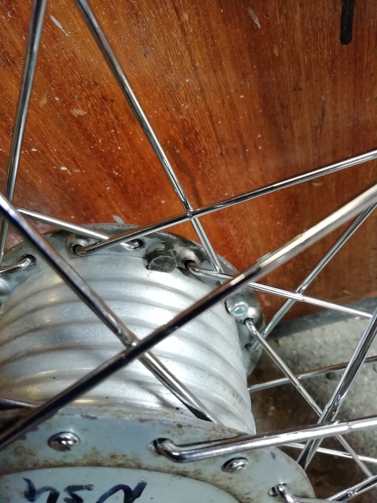
Very pleased with the rebuild although it took a long time. They were able to lace the spokes in a different pattern that gives more room for the heads of the sprocket securing bolts.
RE laced spokes giving more room for sprocket bolts.