Tuesday, July 28, 2020

Norris ignition points

There are two types of contact breaker points in the Quickly, the later type 2 are described in my section testing the motor, the. Type 1 or Norris points are dealt with here. I'm renovating the magneto back plate and it will need a new ignition coil. I've removed the old one here to make access to the points easier.

Norris points feature an eccentric screw post allowing adjustment. They are retained on The back plate by a removable brass pivot post and a retaining screw.

Norris points in position (ign coil removed) Note eccentric adjuster screw located in adjustment notch in contact breaker base plate (centre). to left of the brass mounting pins and C clip. Yellow fixed point wire attaches to the base plate with the wire down-most so it can slip neatly beneath the  lighting coil to connect with the condensor.

Moving point connections, note the small bolt enters from closest to the points towards the lighting coil


Remove the C clip and washer from the brass mounting post. Just push the open end backwards using a broad screwdriver blade.
Remove the C clip by levering backwards. Note the order of attachment to fixed point, the leaf spring of the moving point is  outside the lhs insulation washer and not as shown below!

Loosen the small bolt passing through the fixed plate using  2 x 5.5mm spanners but don't remove the bolt yet. This should let you pull the moving point upwards and off the brass pivot post, slipping the leaf spring from behind the 5.5mm bolt head as you do so.
Unscrew the fixed point retaining screw.

Loosen the brass pivot post using a 7mm spanner.

Remove the brass mounting post and lift out the fixed plate. You can then remove the small 5.5mm bolt completely keeping careful note of the order in which the various washers and yellow wire tab contact are fitted. Note that although the bolt passes through the fixed point and the wire is attached here, it makes no electrical contact with the fixed point plate due to insulation sleeves and washers which must be refitted in the correct order. The yellow wire is connected electrically only to the moving point.  From the left to right (ie from contacts towards lighting coil) the order is bolt head, small washer (moving point leaf spring), insulating washer with spigot. (Fixed point plate), insulation washer, yellow wire contact, washer, spring washer, nut. I did take a photo but got it in the wrong order!! Note the leaf spring should be the other side of the insulation washer towards the bolt head.
Components of moving point connection- Note leaf spring should be to the left of the left insulation washer so it makes no contact with the fixed point base plate.

Pivot post and fixed point base plate removed


Old points removed The cut out into which the eccentric adjuster fits is typical of points ULZ115/1Z
When you lift out the fixed plate take care that the eccentric adjuster which fits behind doesn't come off too.

Eccentric adjuster plate and the circular recess into which it fits.

This is simply a round flat plate with a screw post eccentrically mounted. The plate fits into a circular recess in the back plate and the post engages with the fork cut into the fixed plate. Moving the post screw rotates the plate beneath opening or closing the points. Clean the circular adjustment plate and also the magneto back plate where the fixed point plate and adjuster plates fit. Apply a smear of hmp grease in both areas, use grease to hold the adjuster in place.

Its not time to start reassembly. Genuine points Norris numbers ULZ115/1Z and ULZ 185/1Z are now quite expensive at almost £20 inc postage so its appropriate to look for substitutes. This means that it is essential to compare the old points with the new and make sure they will fit. I first bought a set from France Dudoco no 664 but despite the labelling these didn't fit, because the base plate was different. I think I will hang on to these as I might be able to modify them later.

Fixed points compared Same size overall but more metal on the replacements (upper) compared with the original (lower) and in particular the adjuster slot on the original (ULZ115/1Z) has become a hole on the Duduco points. Careful trimming of the base plate should allow these to fit. However I didn't use them.


I found a cheaper set from Italy numbered 4731 and these are a good replacement. The base plate on the Italian 4731 points was the same except that it had a nylon insulation plug already fitted. This dispenses with the two cumbersome insulating washers used to fit the old points  and makes fitting easier.
Italian points base plate. Note insulation plug
Old points fixed point base plate- note no insulation plug.

Before starting check that the point contact surfaces are clean. Many are covered with a preservative to stop them rusting. Wash this off with clean alcohol. Its easier to install the fixed point if you loosely assemble the 5.5mm bolt and its connections before fixing the plate into position. Fit the pivot post loosely so the fixed point can be swivelled round allowing easier access to the fiddly 5.5mm bolt and its connections.

New fixed point in position but swivelled round to allow easier access to the 5.5mm bolt and its connections
 Fit the 5.5mm bolt washers and yellow wire tab but don't tighten the bolts yet.


5.5mm bolt and connections in place
Swivel the fixed point plate back into position such that the eccentric adjuster screw post locates in the fork of the fixed point plate and secure with the adjusting screw and by tightening the brass pivot post. Check that the shoulder at the bottom of the post passes through the fixed plate so that it will be free to move during adjustment. Check that the yellow wire and tab do not make contact with the magneto anywhere except the 5.5mm bolt.

Apply a little grease to the brass post and fit the moving point by slipping it over the brass post, compress the spring leaf with a finger and slip the hooked end over the shaft beneath the head of the 5.5mm bolt and between the bolt head and the insulating washer (if present) and NOT between the insulating washer and fixed plate! My new points have an integrated insulation plug making incorrect assembly impossible. The cut out in the leaf spring will slip over the bolt shaft and you can then tighten the 5.5 mm bolt.
Moving point installed

Make sure that the moving point is seated on the pivot pin and secure it with its circlip.

Compressing the circlip to secure the moving point on the pivot post.
Check that the points meet squarely and make good contact

New points meet squarely at the same height

In my case I still need to refit the ignition coil and solder all the wires I've detached. If you've not stripped the magneto base plate obviously you would just refit it to the motor, fit the flywheel and adjust contact gap and ignition timing.


Monday, June 29, 2020

Crankshaft rebuild, big end replacement repair.

In rebuilding the crank, I'm being guided by a very useful Youtube video https://www.youtube.com/watch?v=9h-AbRQLGgA
and this instructable: https://www.instructables.com/id/Rebuilding-a-pressed-pin-crankshaft/

I'm trying this job simply to see if its possible- its either this or junk the crankshaft I have simply for having worn bearings! However, bear in mind that any rebuilt crank will need to be reassessed for shimming requirement because it's unlikely to be reassembled to exactly the same width. Most untouched cranks have a width of 1.19 inches measured between the crank entry points.

Before even starting to dis-assemble the crank, its important to have an eye to the rebuild. Firstly, assess the crank you have. Make sure the threads are good and if they need redressing sort them out. Check the key way making sure it's not enlarged or uneven and that the key fits tightly and doesn't wobble. Finally check the bearing lands or contact areas and the regions where the oil seal lips will run. Minor scratching often occurs on the lands during fitting or removal, it's not particularly serious although it can make a shaft stick during assembly, just polish it off with a light file or emery. Scratches or pitting in the oil seal lip running area is more serious as the seal needs to be gastight. Unevenness, or pitting here will promote leaks and rapid oil seal wear. Check any remedial action has been successful before even trying to change the big end.  Check it runs true and that the shafts arent bent.
The cost of a conrod/big-end kit is about £80. A complete new crank is £130 so not quite twice the cost, and it comes with a more modern little end roller bearing. Consequently unless you are sure your crank is basically sound, it's probably better to buy the new one. However, I wanted to try a rebuild so in the spirit of experiment I moved on.

When tested at the journals very close to the webs (and inboard from the bending) my shaft was trued pretty much perfectly with a run-out of the order of 0.02mm. Despite this the webs weren't perfectly aligned- there was some swivel obvious around the crank pin

Webs slightly swivelled
There was also some non parallel alignment between them, although strangely this was more obvious side to side rather than top to bottom.
The gap between the webs varied from 7.88 to 8mm depending on where it was measured.
Distance between webs

Inter web distance.
Interestingly, I think these various out-of-expected orientations were somehow self-cancelling as the the shaft ran true despite them. The gap between the webs is about 8mm and an 8mm brass rod or flat bar slipped between them. I decided I could use the bar as a depth guide during the re-pressing stage; it should slip snugly snugly between the webs to keep them parallel without over-pressing.
8mm brass bar tested as spacer.
 Measuring between the webs at the crankpin showed the gap here should be about 14.2mm

There is a groove at the top of the webs where the thrust washers locate- distance between webs here...14.24 mm
When dis-assembling, the first problem is how to support the crank in the press. I could see two approaches; best would be to support one web such that you can press the pin through that web whilst supporting, and thus pressing only on that web. To do this I made use of the grooves machined inside the webs above the crankpin, these are hidden when the crank is intact but I can show them below on the crank once disassembled.

Inside of crank webs, note the edge grooves (3mm deep)surrounding the crankpin locating hole. Square indentation at the top is where the thrust washer locates.

I used two lengths of flat steel bar to make a suitable support, 4mm and 8mm thick, width isn't critical but 40-50mm should be fine. I cut 30cm lengths from each. The 8mm bar will simply slip between the webs below the crank pin and needs no modification.

I cut a 26mm slot in the centre of the 4mm thick bar such that this will slip down between the webs and into the grooves flanking the conrod. Positioning this bar is hard to describe when the crank is intact so here its shown on a disassembled one. Probably best to use a wider bar so the slot doesn't weaken it so much. Hey, you use what you have!

4mm bar with recess showing how its intended to locate in the internal grooves at the top of the webs.

This slot will need to be filed for a good fit.
The bars and crankshaft are assembled on the pressing table as shown. Since the 8mm bar is thicker and not recessed into the web it lifts the web higher at this side.  The 4mm bar then needs to be lifted to ensure that the crank is held level. For my first attempt I used two lengths of 8mm round or hex bar. It worked, but I think better is to replace them with two pieces of flat 5mm bar shaped to fit more closely against the conrod for more even support and these are shown below. In fact if you calculate the thickness needed; a 4mm bar recessed into a 3mm groove should project only 1mm and thus need a 7mm flat bar to pack it up to the same height as the 8mm bar between the webs, but it seemed to work OK at 5mm. I can demonstrate that below- again on a disassembled shaft.
Manner of assembling the packing pieces prior to pressing, shown here on a separated shaft, the 4mm bar lies in the grooves and the packing pieces fit around the conrod and protect it from the pressure.

However, I couldn't tailor these plates until I had separated the shaft, so for my first attempt I used the rods assembled as shown. This did work but led to some bending in the 4mm bar, hence my wish to use the flat bar for support in my next attempt.


Thicker bar slipped between webs and close to crank pin, thinner bar slipped down above the conrod but engaged with the internal ridge on the webs
Supporting the upper web using flat bar instead of rod.
Use a thin shaft to press down on the pin and push it out through the conrod and lower web but make sure the shaft is long enough that it can press the pin out without allowing the press to contact the thread on the end of the crankshaft
Pressing on the crankpin
Pressing the pin through- had to stop here as the press is close to contacting the thread so switched to a longer  probe. Could then flip the webs over and press the pin out from the second web.

Pressing the crank pin out from the second web

This approach of supporting the upper web only did work but whatever I did the support bars always bent. I'm not happy with these bars being single use So after I'd dismantled one crank I tried a second using the press plate alone. I found the larger round plate hole could accommodate the shaft and crankpin together whilst supporting the lower web on both sides.

Press plate position above hole in th e anvil. Largest hole selected


Crankshaft can fit in hole, shaft passes through, crank pin is free to be moved downwards whilst the lower web is supported all around. Fit press pin and compress. Crank pin has to be moved through both webs and do takes more pressure. A 10t press was sufficient. 


Pressing on the crankpin from above now first closes up the webs and pinches the big end. Once that has tightened up, further pressing pushes the pin through both webs at the same time and so requires more force than the first approach. However it worked well, the pin exited the upper web, the upper web and conrod could be lifted off. The pin was then pressed further down and out through the lower web.

Removing the con rod obviously scattered the big end roller bearings everywhere. These rollers were held in a cage which was also detached. The crank pin shows clear deterioration and pitting where the rollers were positioned and this explains the wear I had detected.

Separated crank pin

I cleaned up the separate webs using the brass wire wheel to remove rust and clean out the groove for the thrust plates before reassembly. 


I checked that the webs hadn't been bent by the process and both internal faces still fitted well together.
Checking the webs for flatness and fit


To start reassembly I first pressed the crankpin into one web. This weas simple because I could just use the press plate allowing the shaft to hang through the opening.


Pressing the pin into the first web, use oil to ease it in.

This presses the pin into the table until its tip emerges flush on the other side so its hard to go too far. Its really important to polish the end of the pin and the inside of the web, they must both be absolutely clean. Use light grade oil to help ease them together.
Crank pin pressed flush
Position the thrust washer on the inside of the web and then fit the conrod and big end. Here I got a surprise as the, con rod and bearings were different from those I removed, the rollers were larger and the cage was absent.I could then press on to reassembly which is much easier to support because the web can lie flat on the press table as the pin is pressed in.
Big end roller bearing cage and its rollers (upper two). New bearings are shown below and are much bigger, the cage is not used.
I could slip the rollers inside the conrod packing them in motor assembly lube
New rollers slipped inside the conrod to form the new big end.


Apply the second thrust plate then clean and position the second web on the crankpin, ensuring all is clean and polished and using oil as before. The upper web needs to be positioned as closely as possible to alignment with the lower web and then pressed on.
Placing the second web- align with the first before pressing
Make sure the webs are aligned as closely as possible and press down. Once the web is on sufficiently that there is no possibility of the rollers falling out I removed it from the press and checked the alignment. It had skewed slightly  but I was able to get this back close to parallel by squeezing  the webs in the vise. I checked that the shafts ran reasonably close to true and then returned it to the press. I inserted an 8 mm spacer (rod or bar) between the webs and pressed down to complete the assembly, again the crank pin is pressed down to flush.


I pressed until the gap between the webs at the top of the thrust plate was 14.2mm
Closing up the webs over the new con rod
Crank pin flush in opposite web.
Finally, I had to check the shaft and re-true. I had hoped that my intermediate truing adjustment would mean that minimum adjustment would be necessary at the end. This didn't work out that way and I doubt I would bother with the interim adjustment next time. Despite my best efforts the crank was well out of alignment and needed a lot of manipulation to true it. The recommendation here is to use a heavy but soft-faced hammer to strike the webs as described. In fact I couldn't move them at all with a rubber mallet or copper hammer so in the end I was forced to tap with a lump hammer to  swivel them as needed. This did work and I ended up with a shaft that was trued within  acceptable limits. Wobble measured 5cm from the webs was less than 0.1mm (0.05 achieved).
At this stage I checked the crank width as above. I had over compressed the crank slightly and the thickness across the webs, measured at the shaft entry points was now 1.79“. I will use a 0.02"shim (smallest in the set) to compensate.

The con rod kit comes with a new small end bush which will need pressing in and reaming. It seems a good fit and is too small for the Gudgeon pin so reaming is needed. I've been supplied with some in the past that were too large even before fitting and accepted the pin as a loose sliding fit. I had assumed that these would tighten up due to "crush" when fitted but sadly this was not the case: fitting resulted in negligible compression of the Bush and so play in the small end wasn't eliminated. It had to come out again. The new one should be fine though and can be fitted as I've described under motor rebuilding.

New Bush right, lacks the splash lube holes present in the old. I will drill new ones after fitting and before reaming. 

 The only difference is that this bush lacks the 3 lubrication holes of the original and so will need to be drilled through, using the conrod splash lube holes as a guide... after fitting and before reaming.


Monday, March 9, 2020

At last! Strip and rebuild of my bikes original motor!

Well having fought two other motors to a standstill, its now time to look at the motor that came with my bike. This has an obvious oil leakage from behind the magneto so the oil seal there at least is gone. I want to renew all the gaskets and seals and obviously whilst doing this its sensible to change the bearings and any bushes as appropriate.

I'm going to take this fairly quickly as a more detailed description of a strip down has been given already- this is mainly to present and organise my pictures so I can use them as a record in case needed.

Firstly remove the chain sprocket using the puller

Sprocket extractor
Remove the cylinder head, 4 nuts and washer
Removing the head
... and pull up the cylinder block
Pulling off the barrel
releasing the piston.
Barrel off
I numbered the bolts from 1-8 clockwise around the motor starting at the bolt lying at the rear cylinder block stud as number 1- shown here.
Numbering the bolts, no 1 id top centre of photograph, numbering proceeds clockwise.

I stored the bolts in order using a cardboard strip- in case interested, in this motor at least the bolts have the following lengths (I'm assuming that the bolts were in the right holes to begin with!).
1: 80mm
2: 55mm
3: 80mm
4: 80mm
5: 80mm
6: 55mm
7: 72mm
8: 80mm
Bolts 2 and 6 enter the steel case inserts and in my view really need to be 65mm
Crankcase through bolt 50mm


Bolts stored in order
I removed the brake lever and its circlip (not shown) but left the inner circlip securing the pedal driver to the case and removed the case by tapping it with a rubber mallet. Unlike my other motors this one separated relatively easily.
Removing the lhs case


LHS case removed, clutch cup and 80t gear revealed.
Remove the "Omega" clip at the bottom of the clutch cup- press down and inward.
Tab of omega clip visible in notch, press in and down with a screwdriver.
remove the clip and..
Clip removed
... pull off the clutch cup
Remove the clutch cup- it just pulls off.
Note the shim on top of the 80t mainshaft gear (don't lose it)

80t gear shim
Remove the clutch by compressing with the special bracket using case bolts 1 and 3- do not over compress or you will cause the clutch to slip in the next stage.
Fitting the clutch compressor, use bolts 1 and 3
Fit the gear locking tool (home made in my case) to lock the 80t gear using bolt no 4 and an 8mm bolt through the engine mounting hole. Not shown here- see previous rebuild post.
My home made clutch locking tool.

Clutch locker in use (old picture)

Unscrew the clutch nut abd take off the two spring washers. Remove the clutch release mechanism

Clutch release mechanism, spring ends (bearing on lower) and spring.
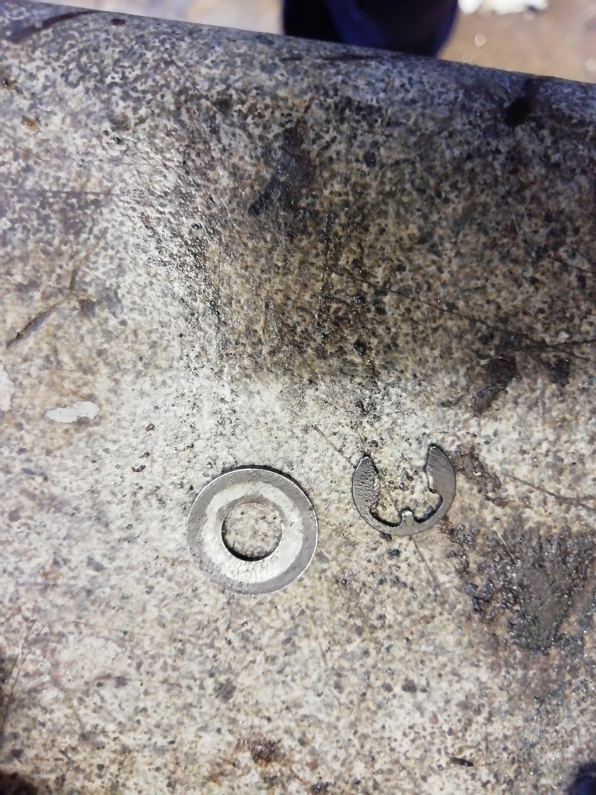
Turing to the other side of the motor, remove the circlip and washer from the end of the gearchange pushrod so that the change lever is disconnected.
Gear change lever secured to shift rod

Close up, E clip and washer

 E clip and washer removed
On the lhs of the motor the 80t gear should just slip off. in this case it was unusually stiff, you may need to push it down and twist to release the gears . It helps if the motor is in neutral and I suspect this one was somehow tangled with the gear change dogs. I made a mental note to inspect the gear change system later.

Removing the 80t double dogged gear.

continued


Removing this gear usually leaves the main shaft in position- in my case it seemed to fall out of its bearing inside the case, the gear and dog fell loose and the bush separated from the gear. I couldn't remove all these parts until I had further separated the cases.
I went on to remove the clutch centre- the cover just lifted off.
Clutch basket

The clutch turned out to be a five plate unit- probably because this was the higher powered higher compression later motor
Basket removed- 5 plate clutch.
The clutch centre is held on by its circlip.
Clutch centre, held by circlip onto crankshaft
I removed the circlip with circlip pliers.
Removing circlip, note that mainshaft is in position but seems to be loose and is drooping down. It fell out completely moments later
 Once the circlip was removed the clutch centre should slide off although it may need levering. In this case it simply lifted off with a gentle hand pull.
Clutch centre
There should be an O ring below the clutch- at this stage I couldn't see it so I continued with the strip (found it later).
clutch centre removed

At this stage I turned the motor over to remove the centre to rhs case bolt and nut. As I turned the motor the main shaft simply fell out of its bearing - this hasn't happened before. I unscrewed and removed the short centre to rhs case bolt and its associated lock washers.
Crankcase internal bolt

Note the main shaft became loose and dropped out as I turned the cases to work on the other side.  To remove this I needed to split the remaining two cases.

80t gear removed, mainshaft has fallen out.

To my surprise a gentle tap was all that was needed to start the cases separating - it should have taken more than that so I suspect this joint hadn't been gas tight either!


Cases beginning to separate

...and still separating..
I could now remove the main shaft, the gears on it just fell off. It seemed to me that it had been jammed on the gear change fork which looked a bit worn, I will need to compare this with those from other motors.

Once the centre case was removed the lay shaft double gear unit could be lifted off its shaft, note the shim on top of this gear unit and once again there was no shim below even though the manual shows one in this position. I now know better than to try and replace it!
Layshaft double gear column- shim from the top, no shim beneath.

The crank shaft also lifted out-much more easily than in previous motors. I did find the clutch O ring on the crank shaft just below the splined section. This was in very poor condition, brittle and marked from the splines.
Found it! The clutch O ring wasn't missing but hard and flattened in the groove on the crankshaft below the splines. 
The pedal shaft lifted out easily

The circlip and thrust washer were removed from the gear change push rod so that the fork can be lifted off. Note that the parts book shows only a circlip in this position but in every motor I have stripped I have also found a flat washer mimicking the attachment system on the gear change lever side.
The gear change fork should slide off although in my case the shaft was a little burred and the fork didn't come off easily. I wondered if this had meant that the gear change was unusually stiff and I'll investigate  polishing to improve the slide. If this doesn't work I'll need to replace  some of these components; rod, bush or fork.
Washer and circlip from gearchange rod

I tapped out the main bearing from the rhs case, The oil seal in this position had simply fallen apart and this explains why the motor had leaked in this position.

At this stage I cleaned all the cases, removing old gasket and gritty grease deposits. I could then tap out all oil seals and bearings.
More of a surprise was that the crankshaft oil seal mounting hole below the magneto was slightly out of round and cracked top and bottom. This could have been the cause of the seal failure. I may have to replace this  case, but as this is the case with the engine number stamped on it, any swap would
 obviously change the originality so I'd like to keep it if at all possible. 

Oops this opening and oil seal mounting hole is distorted and cracked. The broken seal has been removed.

I managed to restore the roundness using a socket which was exactly the same size as the seal, tapping this through a few times restored a nice rounded profile. I will use some jointing compound when I replace the seal to try and block and leakage along the cracks and hold the seal in place. Hopefully it will not be significantly off centre
Socket fitted perfectly, tapping it through to restore shape
o

Finished, socket moves easily through with even gaps

I also needed to replace the pushrod oil seal. In this case I didn't have a new manufacturer's seal so I removed the gear change lever by knocking back the positions where the case had been peened over the pivot rod
Gearchange rod oil seal removed- visible below the fork
.

Knocking back the peening that holds the fork pivot rod prior to removing the fork
I could then line up  a drill and use a flat-end mill to mill the hole out to 14mm.
Oil seal hole milled out to 14mm using a flat end mill
I could then fit a normal (non metal cased) seal 14x6x3 and refit the gear change pivot.
14x6x3 oil seal inserted

Changing the bearings and oil seals in the other cases was straight forward and proceeded as described previously, except that two bearings (mainshaft and rhs crank shaft) were just too loose and fell out again even with mild heat. They would certainly not stay in position in use so I secured them using Loctite 620 heat resistant retaining compound. I polished the gear change rod and re-reamed its bush to 6mm. This ensured that the rod could slide easily through the bush and the fork slide easily along the rod. I honed the I side of the clutch turret and pedal shaft exit on the clutch side crankcase as both were scored and had been leaking.

I removed the 4 O rings from the driver unit, 2 large external and 2 smaller internal. Simple matter to replace.
Brake pedal driver and o rings removed
Use plenty of oil and insert the driver into the clutch side crankcase and secure with the inner circlip. The unit is stiff to turn with new O rings but I. Hoping it will ease up with use. Ive found that its easier to fit the case if this brake driver unit is fixed in the case and cant slide inwards along the pedal shaft. Use plenty of grease on the pedal shaft, use the special insert wedge if you have it.
Driver inserted to lhs case and retained with circlip
I replaced the clutch cup O ring. Opinion is divided as the old rings seem to be a better fit, but in this case the seal had clearly been leaking so I replaced it.
Clutch cup, old O ring top, new bottom. Different sizes
I removed the clutch bearing using two sockets. A 30mm socket fits over the spring base to press (just) on the outer race of the bearing. A 6mm socket on the other side fits inside the bearing to press on the  spring base. Using a vice I could press the spring base out of the bearing and into the larger socket.
How remove the clutch bearing- spring base emerging from the bearing and fits inside the 30mm socket. Extraction shown  mid-way.
Use an appropriately sized socket to press the new bearing onto the spring base, press only on the inner race.


The layshaft bottom dogged gear slipped off the shaft and the bush fell out if it. I was concerned that this shaft may be worn but measurement showed it has a diameter of 11.96mm all the way along. This doesn't seem to be much wear so I will reuse it even though it seems a loose fit in the case bearing. The new dogged gear bush 21t is a much tighter fit in the gear and needed no retaining compound when pressed in with the vise. The bush was too small to slip onto the shaft at all so I  reamed it to a smooth sliding fit.
Layshaft components, dogged 21t gear has lost its bush which just fell out. New bus is a tight fit. New bush upper, old bush lower.
Before starting the reassembly I applied assembly grease to all the bearings
Assembly lube added to bearings in the RHS case
The gear change was already assembled so I assembled the main shaft including the large shim below the dogged gear and the smaller shim above it. I added the sliding dog  ensuring that it was the correct way round (recessed centre downwards)
Adding the mainshaft
Latching the gear change fork into the dog, add the layshaft and pedal shaft, rotate everything to make sure it all drops down into  position.
Gearbox assembled- this is a bit fiddly but the dog will engage with the fork and the lay shaft and pedal shaft will mesh.
Use a suitable sealant to stick the gasket to one face of the case, and smear the other case with a film of sealant as well. I used Blue Hylomar but didn't really like it as it tended to lump up- perhaps its too old. In the end I used Wellseal brushed onto each case. I could then fit the crankshaft and assemble the centre and rhs cases.
Adding the gasket
In the event I found the new bearings were too tight on the crank to allow it to be inserted by hand and my puller didnt work. I chilled the shaft in a -20 deg freezer for 90 mins and used a heated socket to contact warm the bearing. The crank then slipped in easily.
Centre and RHS cases assembled- Wellseal illustrated.
Pay attention to the top end of the gaskets where they pass up to the cylinder block base. These can slip out, make sure that they are in place. Also make sure the clip of the sliding unit fits between the two lugs in the case and that the sliding member is fitted the right way round- narrow side downwards.  Secure the two cases with the through bolt. Don't screw this up tight to avoid distortion of the cases.
Through case bolt secured but not over-tightened.
Turning the motor over
Motor from the LHSnote layshaft and gear change rods in position in holes in the case, pedal driver spring clip engaged between lugs in the case
I slipped the O ring onto the main shaft
New O ring on the crankshaft
and pushed it down by hand
Sliding the O ring down
It was pushed finally into place by adding the clutch centre and pushing that down; securing it with the circlip.
Clutch centre fitted and secured with the circlip.
I added the clutch basket and plates
Clutch basket in position
Add the 80t dogged gear and press it down and rotate to make sure its engaged. Do not forget the shim on top of this gear.
80t gear fitted and shim added
I applied assembly lube on the other crank shaft bearing and Wellseal to the edge of the case.
Assembly lube on LHS case, Wellseal added to flange
Before sticking the new gasket on.
Gasket stuck on
I could then assemble the clutch on the crankshaft- and Yes, I had forgotten that and had added the Wellseal too early!
This is the gear immobiliser fitted into place.Tighten the clutch nut until the clutch slips and the piston starts to move.
Locking device in use, tighten the clutch release mechanism until the clutch slips and the con rod moves.
Fit the clutch cup and omega clip and grease the inside of the pedal shaft opening and the clutch turret before pressing the lhs case down. It needs to go over the pedal shaft first (use plenty of grease on the shaft and if you have the special wedge use that too). The driver unit is still secured in this case by the circlip and its a tight fit over the pedal shaft. Once the pedal shaft has entered the driver, push over the clutch turret so that the cup enters the turret. Finally as you continue to press down check that the main shaft enters its bearing- I used contact heating again on this bearing before assembling the case to ensure a smooth assembly.
Refit the 8 case screws and tighten these, tighten the through bolt from the right hand side.
Refit the 4 cylinder barrel studs (if you removed them), add the cylinder base gasket- secured with Wellseal, and slip the cylinder down over the piston. I tried using a ring compressor but actually it was easier just to use my fingers.
Add the cylinder head and secure with the 4 nuts and spring washers.


I attached the magneto backplate... This was interesting. The plate has a notch put on in the factory that should align with a notch on the crankcase when timing is approximately correct. I've always had trouble timing this motor and I've been having to use full retard, taking up all the adjustment in the slot even to get in the right ballpark. Similarly access to the points has been hard for adjustment as they don't appear in the centre of a window at max opening. Now that the magneto is disassembled, and the motor is on the bench, it's clear that these slots cannot coincide. When they are aligned the backplate screw holes are completely hidden! I tried another backplate, the earlier type with orange ignition coil and with this alignment was perfect. I am left wondering whether the backplate was changed at some point and the magneto updated to use the newer style black plastic ign coil, but the backplate used wasn't quite right for the Quickly? The old backplate I used to test fit has sadly a dead ign coil so I can't simply fit that one and I'll need to replace the coil if I'm to switch back and regain timing control. In the meantime I'll press on with this one.
Backplate  markings aligned, mounting screw holes hidden. 

Close up, marks aligned, screw hole hidden

Older style magneto backplate, marks aligned, screw hole nicely situated in the centre of the adjustment slot. 
The new black coil will accept a full size HT lead but this is too stiff and inflexible to route around the mag and out of the case. Especially as the Ign coil directs the cable backwards where it has to make a rapid bend against the crankcase. This makes installation of a full size cable very awkward and the rigidity makes timing adjustment very difficult. I therefore installed the thinner cable that Quicklies come with.
Two thicknesses of HT cable
The cap doesn't quite close around the thinner cable so I used a small grommet first, this will fit inside the cap and make a good seal with the cable.
Grommet fitted below coil lead cap

Even so the HT lead is still bent sharply on exit from the coil.

Still I completed assembly, and fitted the motor in the frame. I checked spark, added oil and fuel and hey presto she fired up! For the first time since I've had the bike it runs easily and responds to throttle!! Still needs a bit of a tune and adjustment, and I need to sort out the niggling problems with the wheels etc then it should be finished!!

The Quickly mainshaft only has one oil seal on the sprocket side (not magneto) and it's  12 x 32 x 7

Crankshaft has 2 seals - 20 x 35 x 7 and 15 x 24 x 7. With 2 x 6202 bearings